Besieged by the Duke of Norfolk's army of 3,000 men, the Paston family's hold of Caister Castle in the summer of 1469 was doomed. Despite preparing the defenses for nearly a year, the genteel East Anglian family were simply no match for the Duke of Norfolk who could bear down on them with all of the power and resources his title came with. Stocked with longbows, crossbows, and even handgonnes, the Pastons had turned the all-brick Caister Castle into a fortress. They had hired four professional mercenaries the previous fall and, by the spring--just a few months before the siege--they showed some signs of training hard as evidenced by John Paston III's request to replace "four or five steel crossbows." On September 26 though--37 days into the siege--surrounded, low on supplies, and having lost a devoted servant to a crossbow bolt, the Pastons were forced to accept Norfolk's terms of surrender.
The letters surrounding the Siege of Caister Castle offer a glimpse into the defenses of an English genteel family's property during what is now called the Wars of the Roses. It should be noted here, however, that the Duke of Norfolk's capture of Caister Castle from the Pastons was the result of a decade-long dispute over land claims, and thus, with only a small exception, had nothing to do with who sat on the throne. The one exception was the timing: Norfolk seized his opportunity to siege the castle when word got out that the Earl of Warwick had captured King Edward IV at the Battle of Edgcote and the kingdom was without a ruler for the next couple months. Regardless, this was just one of several fights that the Pastons found themselves in during the 15th century. As during this siege, the Pastons also recorded the defenses of their castle at Gresham two decades earlier, in 1449 (six years before the traditionally understood start of the Wars of the Roses, at the First Battle of St. Albans). In both instances, the letters highlight the family's reliance on a piece of military technology not normally associated with late-medieval English history: the crossbow.
While the longbow understandably reigns supreme in the popular history of late-medieval English warfare, it did have its drawbacks. In early 1449, Margaret Paston wrote her husband, John Paston I requesting military supplies to shore up the defenses of Gresham Castle. They rightly suspected that a local rival, Lord Moleyn, had designs on their property, especially after they discovered that he was amassing men and equipment at a nearby manor. In her letter, Margaret requested "crossbows and windlasses to fire them with, together with quarrels, because your houses here are so low that no-one can shoot out with a longbow." Despite the renown of the longbow (Agincourt was only 34 years earlier), they seemed better suited to open battlefields than to defending buildings. While Gresham Castle fell without a single quarrel shot, the Pastons clearly did not abandon the use of crossbows.
Twenty years later, to defend their castle at Caister, they not only relied on them, but they may have been responsible for the two casualties on the Duke of Norfolk's side. Interestingly, to prepare for its defense, Sir John Paston (also referred to as John Paston II) hired four mercenaries whom he described as “experienced men, cunning in war and feats of arms, and they can shoot guns and crossbows well; they can mend and string them; they can build defences or anything else that is needed to strengthen the place.” Sir John did not hire longbowmen, but rather, men with experience with crossbows and guns--weapons better designed to defend their castle with. Despite their expertise, they clearly could not repair the four or five crossbows that got damaged that winter or following spring as the castle's defender, John III, wrote to his brother asking to have them repaired in London by a "maker of steele bowys." It is in this letter that John III describes them as "steel crossbows," and his brother's in particular as a "great bow."
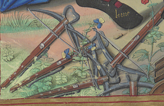 |
| Pétrarque, Des Remedes de l'une et l'autre fortune, traduction rouennaise anonyme en français. Bibliothèque nationale de France. Département des Manuscrits. Français 225. Fol 78v. 1503. |
By the 15th century, steel crossbows were catching on in Europe. They had been around for some time already--perhaps as early as the 13th century--but by the 15th century, more reliable steel production had caught up with the demand. While they did not outright replace the more traditional wood or composite crossbows--the latter seem to have remained popular for hunting--steel crossbows were favored for war due to their heavier draw weight, lower cost, and faster production time (compared to composite, in particular). While soldiers clearly favored them by the end of the 15th century for these reasons, they did have some glaring disadvantages. While steel production--notably an understanding of heat treatment--was better, it was not unheard of for a bow to break under pressure. Additionally, while a 1,000 pound (454 kg) crossbow sounds impressive, due to mechanical inefficiency, it performed only marginally better than a top-tier composite bow. Again though, speed of production (not having to wait for the glue to cure in a composite bow) and cost were probably the most deciding factors for soldiers, or those who hired them, to buy steel crossbows.
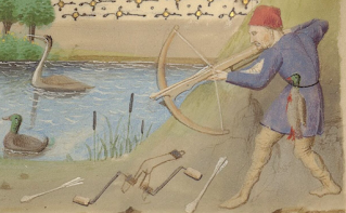
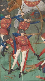 |
| Pierre Choinet, Le livre des trois âges, en vers. Bibliothèque nationale de France. Département des Manuscrits. Smith-Lesouëf 70. Second half 15th century. |
The Pastons were those people who found the argument compelling enough to invest in steel crossbows. While it can't be known if they used steel bows, in particular, at Gresham in 1449, it is clear that they were employed at the defense of Caister Castle in 1469. At Gresham though, the letters offer one more insight into the use of heavy crossbows in England: the spanning device. While contemporary depictions of crossbows show a range of spanning methods (from hand-spanned to goatsfoot levers, cranequins to windlasses), Margaret Paston specifically requested windlasses--a pulley-based spanning device. Her knowledge of crossbows and spanning devices might be explained by the fact that she grew up around them (she was a cousin of the infamous Sir John Fastolf) or perhaps she learned about them while discussing strengthening the defenses of Gresham with a military-minded confidant. Regardless, the fact that she requested them suggests a common knowledge and availability, if not in East Anglia, then certainly around London where her husband primarily worked. In the artwork of the period, windlasses seem most popular around France and the Low Countries (i.e. Belgium and the Netherlands), so it seems probable they were similarly known in England. The only other spanning device that could handle the heavy draw weights of a steel crossbow (800-1200lbs) was a cranequin, but these are more often than not associated with central Europe--German-speaking states in particular.
Rationale
About five years ago, I co-founded a medieval living history group--the Paston Project--with a bunch of friends who have a similar interest in medieval English history. The purpose of our organization is to recreate some of the experiences of the Paston family and the world around them, during the third quarter of the 15th century--some of it military, but the bulk of it civilian. As we only wanted to represent a couple of the actual Paston family members, the majority of our group took on personas related to the household. I started as a cook and a longbowman, but as we already had some longbowmen, I began considering other portrayals to widen our interpretation. Reading the Paston letters, I saw a few solid references to their use of crossbows, and became entranced. As a guy who loves to make stuff, I was intrigued by the challenge of making my own crossbow, so I did just that: I built a 200lb (91kg) steel crossbow. It was truly a joy to learn about crossbows by building one, as it was to shoot it--so much so that I entirely rebuilt it to really perfect the design. That said, I had a little whisper of a thought that kept popping up in the back of my mind: this crossbow isn't really representative of the steel crossbows used by the Pastons. Not only did I compromise a little historical accuracy for safety by making the roller nut out of delrin and keeping the protective rubber sleeve around the center of the bow, but it is still such a low draw weight that I can hand span it (i.e. pull the string back by hand). In the Paston letters, Margaret specifically requests windlasses. This conforms to the broader historical understanding that crossbows meant for war should be very heavy--at least 800lbs (363kg). While hand-spanned crossbows might work for hunting, they're less useful for war as basic armor like padded jacks and maille stand a decent chance of stopping bolts shot from them. While I wouldn't mind making a heavy steel crossbow, my problem was sourcing the bow.
The journey to find a "maker of steele bowys" involved a fair amount of emails, Facebook posts and messages, and plenty of dead-ends: truly the makings of a great story. When I came close to buying a steel bow from Jens Sensfelder himself, our geographic differences posed too great a challenge to complete the sale (for those "not in the know," Sensfelder has not only published a book on crossbows, but the steel bows he makes are considered the gold-standard in the European crossbow building community. He's also one of the only artisans out there who makes reliable, 100% accurate, heavy bows). When my hopes were dashed and I was about ready to give up, I received a message request from someone in a crossbow building group I had posted to on Facebook--he had a spare steel bow made by Sensfelder that he might be willing to sell to me. It's here that I'd like to take a moment to offer my appreciation to this seller as he not only sold me the bow, but he guided me a number of times in the process of building mine. While I had experience in making a crossbow, this one would be five times heavier, so I really didn't want to screw things up. I owe a fair amount of my success in building this crossbow to him. Needless to say, at long last I was able to obtain a proper, heavy steel bow.
(As a side note, for anyone interesting in learning more about my medieval group, the Paston Project, please check out our Facebook page here (website coming soon!). Additionally, if you simply want to learn more about the Pastons, I highly recommend picking up a copy of A Medieval Family: The Pastons of Fifteenth-Century England. For the actual letters, albeit digitized, check out Paston Footprints here. This is where I obtained quotes of the letters from, in the above paragraphs)
The Crossbow
The crossbow is a fairly basic piece of technology, albeit deadly. It's composed of only a few main parts: the bow (also referred to as a prod), the tiller (or stock), roller nut, and trigger. Some crossbows--usually earlier ones--used linen or hemp cording to lash the bow to the tiller (as in the example below), while others--usually later--used steel bridles and wedges. Put simply, the string is pulled back to the roller nut which holds it in place with its claw-like hooks until it is ready to shoot. The nut stays locked in place due to the trigger bracing against it (see my diagram under "The Trigger Mechanism," below). As soon as the trigger is depressed and is no longer bracing the roller nut, the nut is allowed to rotate, releasing the string, casting the bolt forward.
.jpg) |
| Crossbow. Object No. H5927. Powerhouse Collection. c. 1470. |
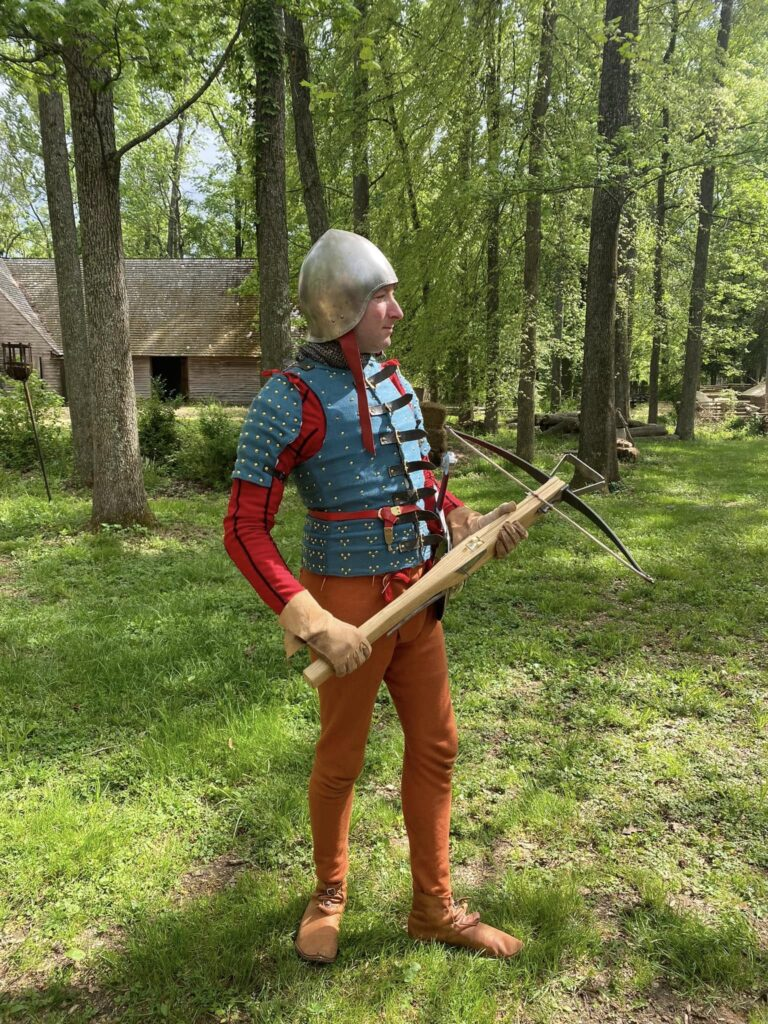
For my crossbow, I chose a simple design with steel bridles. My portrayal in the Paston Project is based on Peryn Sale--one of the four mercenaries that Sir John Paston hired in November 1468 to defend Caister Castle. Since I was interpreting a mid- to late-15th century English crossbowman, it made sense to choose steel bridles instead of lashing the bow with cord. Additionally, since I haven't found anything about Peryn Sale other than his mention in the Paston letters, I figured it would be safer to assume he was a fairly common solder, and not someone with a rich crossbow (especially as the Pastons had to apparently obtain armor for him).
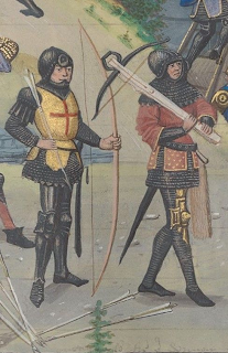 |
| Croniques abregies commençans au temps de Herode Antipas. David Aubert. Bibliothèque nationale de France. Bibliothèque de l'Arsenal. MS-5089 réserve. Fol. 253r. 1476. |
Designing the tiller was straightforward as there seem to be few variations in the visual sources or even extants. It's straight and almost sharply-rectangular, with the exception of the neck, which has a curved cutout on the bottom. It's also thinner than I'd like--thinking entirely too much about my safety--at only two inches (5cm) wide at the widest part (at the nut), narrowing to 1.5 inches (3.8cm) at the butt. That said, this is still slightly wider than some extants which are between 1 and 1.5 inches wide at the nut. This also conforms to the surviving windlasses which have sockets that fit a tiller with these dimensions.
Building The Crossbow
While waiting for my steel bow to arrive in the mail, I sketched out my tiller and began the basic woodworking. For a basic design and some useable dimensions, I highly recommend Sir Ralph Payne-Galloway's The Book Of The Crossbow (you can even find a couple digital copies for free online if you look around). I'm not diving that deep in this article as to list all of the measurements, so start with that and then find some extants in museums like the MET, or if you can get your hands on Jens Sensfelder's book, Crossbows In The Royal Netherlands Army Museum, that will provide some excellent details. While much ink has been spilled discussing the merits and faults of Galloway's book, the dimensions he provided for one heavy crossbow are very much real and can be super useful to see what an original crossbow looked like, especially if, like me, you live in the US and don't have easy access to a lot of originals via museums. Alchem's sketches here could be a great place to start from, too, as can the "Crossbow Building Wiki" here. If all else fails, I'd be happy to answer some questions if you message me. While I'm certainly not an expert, I'm always happy to share what information and experience I do have.
 |
| La Fleur des histoires, de Jean Mansel. Bibliothèque nationale de France. Bibliothèque de l'Arsenal. Ms-5087 réserve. Fol 383v. 1470-80. Belgium. |
For the tiller of my crossbow, I chose to use ash--it seems to have been a common material used in the Middle Ages, and for good reason since it is a hardwood and resilient to splitting. For those interesting in building their own crossbow, I highly recommend buying the ash from Bell Forest. They advertise their ash blanks as a favorite for making baseball bats, if that tells you anything about the wood's strength. Shaping the tiller involved some initial cuts with a table saw and a bandsaw, some with a jigsaw and a belt sander, and all the finer stuff with chisels, rasps, a planer, and old-fashioned hand-operated sand paper. At this initial stage though, I only cut the stock to almost as narrow as it would ultimately end up (minus the final sanding).
The String
During a couple of the evenings after working on the tiller, I also made the string. For this, I used bookbinder's linen thread. I highly recommend Colophon Book Arts Supply's 16/3 linen thread which you can find here. I bought a 250 gms spool of it and have used it to make three crossbow strings and a couple medieval turn shoes and still have a ton left over. Not only has it outperformed two dacron crossbow strings--both of which snapped early into using them on my 200lb crossbow--but it has also held up on my 1000lb crossbow. I truly do not recommend dacron for medieval crossbow strings out of personal experiences with it, but also because it performs differently from linen thread, being significantly lighter. To make the crossbow string, I constructed a jig as recommended in Galloway's book, but also explained in The Modern Armbruster's video here. In fact, if you want to make your own string, just watch his video. Like him, I did not add the auxiliary loops to the ends (which Galloway suggests some had). Not only did the Modern Armbruster not recommend it, but the gentleman who sold me the steel bow advised against it as it just adds weight and reduces the efficiency.

As to the thickness of the string (or more accurately, number of strands in it), Galloway only mentions that the heavy crossbow's string is about 1/2 inch (1.3cm) thick. That's only marginally useful to know, so I did some looking around online and found Hermit's response in the Arbalest Guild's forum to be pretty compelling. His formula accounts for what he refers to as a "safety factor," which is represented by the 4 in the following: Strand Count = (4 X Draw Weight) / String Breaking Weight. The reasoning is that, you don't want to make a string with a breaking point anywhere close to the draw weight of the bow. So for safety, make the breaking point four times the draw weight. The only variable I didn't know in the formula was the breaking point of the linen thread, so to figure that out, I used a crane scale simply by pulling down on a length of the thread over the scale's hook until it broke. With a fairly consistent 32lbs (14.5kg) breaking point, I plugged the measurement into this formula to get: (4 X 1000) / 32 = 125. So what this all means is that, for a reliable crossbow string for my 1,000lb (454kg) crossbow, I needed to make a string with about 125 strands in it. So, when making this string, I wrapped the jig 62.5 times; the result being 62 strands on one side and 63 on the other, for a total of 125 strands. If you're reading this and plan to make your own string, please do not assume a 125-strand string is what all 1000lb crossbows need. The most important thing is that you measure the breaking point of your thread that you plan to use. All thread is different and there's absolutely no guarantee that the thread you have has a similar breaking point to mine.
In one evening--really about two hours--I made one string and held it up to the bow, only to be disappointed as it ended up shorter than I expected. I think the pegs on either end of the jig just bent too much inwards when I was making the string, so I made a new jig--slightly longer and this time added a board to the top of the pegs so they wouldn't be able to bend in (see picture above). The second string, made on this new jig, turned out perfectly. It was just extra gratifying when I measured the thickness of the string in the middle to be 1/2 inch, just as Galloway recommended.
The Bow

When my steel bow arrived and I had finished drooling over it, I had to do some work on it. Sensfelder sells his bows fresh from the forge (and heat treatment), so this means that they are still fairly rough--they need a bit of sanding to complete them. However, the gentleman who sold me this bow encouraged me to not just polish it up, but to remove a decent amount of steel and thus reduce its power. As it was, Sensfelder measured the bow to be nearly 1200 lbs (540kg) at an almost 7 inch (17.5cm) draw. I took his advice and spent probably 15-20 hours meticulously sanding the bow on my belt sander. Starting with 120 grit sandpaper and working up to 400 grit, I kept a very close eye on the temperature (measured simply by feel with my hand) to ensure it didn't get over 212 degrees (100C) which would ruin the temper and could mean that the steel might break under pressure. Simply put, if it got too warm for my hand--well below 212 degrees--I would pause and run some water over it to cool it back down. I also took the moment, when I wasn't sanding, to measure the height and thickness with digital calipers. Needless to say, this seemingly simple task (sand down the bow) took a long time. Ultimately, I declared it done and decided to test the draw weight.
Testing the draw weight meant that I had to be able to span the bow. Without a windlass (I decided against forging one for myself since I'm still new to blacksmithing, so I ordered one instead), the only way to span the bow was to design a spanning bench using a spare 4x4 piece of pine I had laying around and a 2,000lb (907kg) hand winch. Keeping things simple, I cut out a socket for the bow to imitate that of the ash tiller, drilled out a hole behind the socket and added a thick steel bolt to give the wood some extra strength, and then bolted on the hand winch to the opposite side. Using chains and steel shackles (meant for pulling trailers), I spanned the bow back just enough to string it, then slowly released it to its resting point. Swapping out the long chains for shorter ones and a crane scale, I spanned the bow, taking careful note of how far the string moved. When it reached 7 inches (17.5cm), the scale reported a draw weight of 1,004 lbs (455kg). Happy with this, I slowly released it, removed the string, and moved on to the next stage.

Now that the bow was finished, I measured its height and thickness, which I needed in order to make the socket for it in the front of the tiller. Having also measured the brace height (the distance from the bow to the string while at rest, which for me was 3 inches, or 7.62cm) and draw (7 inches), I calculated the angle of the bow in the socket to be 11 degrees. I then sketched out the socket on both sides and rough-cut it out with a jigsaw. I followed this with chisels and files until everything fit perfectly.
The Trigger Mechanism
Next, it was time to tackle the hardest part: the roller nut and trigger assembly. I started by sketching out the whole internal workings of the roller nut on the left side of the tiller. I determined the placement for the roller nut by measuring out 10 inches (25.4cm) from the bow (since the brace height is 3 inches and the draw is 7, the distance from the bow to the center of the nut is 10 inches). Before I could carve everything out, however, I needed to do some work on the roller nut and trigger.


After shaping the nut, I also shaped the trigger and bridles. It's here that I cheated a little. I had originally planned to forge my own trigger, bridles, and stirrup, but between being a little apprehensive of my beginner's abilities with blacksmithing and feeling like I shouldn't have to reinvent the wheel when Alchem sells these parts for fairly cheap, I just bought them (you can find them here). That said, they do arrive "in the rough," so I had to shape them. I roughly shaped the trigger with my belt sander, rounding the main arm. I then used a Dremel tool with grinding heads to shape the tip of the trigger into a little ball. I finally cleaned it all up with some 400 grit sandpaper. For the bridles, I used the Dremel tool and files to open them up a bit to accommodate the thickness of the steel bow. I then reshaped the little fleur-de-lis on the end into a little ball (see picture below), imitating one I saw the Royal Netherlands Army Museum. The stirrup just required some bending to bring it to shape--I didn't do anything to it other than to give it a bit of a polish.

The next step was carving out the socket for the nut and the channel for the trigger. At one point, I had planned to make a steel socket that would be riveted into the tiller and house the nut perfectly, but I decided against it. Some originals seemed to have that (most were made from bone or antler); some didn't. Making one that did have this would mean an even thinner tiller (which, as I mentioned earlier, I was already a little worried about). I chose to leave my tiller on the thicker side, carving out a square socket into the tiller, and leaving almost 1/2 inch (1.3cm) of wood on either side of it. The last thing I wanted was for the nut to rip out of the socket, so I erred on the side of caution and left the tiller thick at the nut. Since I had sketched out the plan for the nut and trigger on the side of the tiller, it was just a matter of removing wood to match the sketch. To start, I added a piece of tape to a drill bit to indicate how deep I would drill out the nut's socket. Using a drill press, I carefully made a few rows of holes to easily remove most of the wood. Once done, I used a chisel to remove the rest of the wood and to create the socket.


Before I could drill the channel for the trigger, I had to finish shaping the rear of the tiller. While I didn't have to worry yet about narrowing the tiller, I did need to cut out the wood underneath. Using a jigsaw, I rough-cut the tiller, but then used a belt sander to smooth it all out. Having nearly finishing the bottom of the tiller, I was ready to install the trigger. Drilling the hole for the trigger was a little more challenging than drilling for the nut-socket. I still used the drill press, but I had to angle the tiller such that the angle of the drill bit matched my sketch on the side of the tiller perfectly. I drilled almost all the way to the socket, then flipped the tiller right-side up, and drilled the rest of the trigger's channel through the socket. Once I had a hole that connected the trigger opening to the socket, it was just a matter of slow and meticulous chiseling to widen the hole and shape it just enough to accommodate the trigger and its eventual movement within the tiller.
When the nut's socket and trigger hole were carved out, the next step was making the side plates. These are more than simply decorative--they help to reinforce the whole trigger mechanism. As 1,000lbs of pressure is placed on the steel pins holding the trigger and nut, that pressure is dispersed into the wood of the tiller as well as the steel side plates. To further strengthen everything, the plates are also riveted in place with 1/8inch (3.18mm) steel rods. I sketched out the shape of the plates based on where the nut's pin and the trigger's pin would be, as well as the steel rods I'd use to rivet the plates on. For the plates, I used 14 gauge, cold-rolled steel that I cut to shape with a bandsaw and cleaned up with a belt sander. I then traced out the plates on either side of the tiller and carefully carved out the wood to inlet the plates. I specifically chose to inlet the plates because the system of spanning--via a windlass--would require a double-hook pulling the string back to the nut, possibly brushing up against the side of the tiller. If the side plates weren't inletting, there's a chance the hook could catch on the plates.

The final step for the trigger mechanism was drilling the holes for the pins that held everything in place. I started by drilling holes only in the tiller: 3/16 inch (4.76mm) holes for the trigger and rivet pins, and then a 1/4 inch (6.35mm) hole for the nut. I would drill a hole halfway into the tiller on one side, and then drill halfway on the other, meeting up in the middle. I paused here to test out the trigger mechanism now that the holes were drilled (which required to me to also drill a hole in the trigger). Everything fit perfectly, which was both satisfying to see, but initially utterly nerve-wracking. Happy with how everything was going, I was ready to transfer the holes from the tiller to the side plates. To do this, I simply traced out the holes on the side plates by putting a pencil through the holes. I did screw up one side plate--the last hole I drilled (because of course) must have skipped a little in the drill press because it ended up about 1/16 inch (1.59mm) off. So after making a whole new side plate, I was more careful about drilling the holes and it paid off. Content with the plates, I riveted them in place with some mild steel rods, cut to size with a bandsaw and slowly hand-riveted with a ball peen hammer. Ideally, I would have used high-speed steel rods (hs steel) for the nut and trigger pins, but the hole I drilled for the nut's pin must have been a little too wide as the pin wanted to slip out. So in the end, I used a 1/4 inch (6.35mm) plain steel rod for the nut, but I was able to use an hs steel pin for the trigger (that one fits tightly without any riveting). While I would prefer that the pin for the nut is removable, should I ever need to replace it, I had to rivet it to keep it from popping out. That said, the pin that holds the most weight isn't the nut-pin, but rather the trigger-pin (which is why you sometimes see the nut held in place by a few strands of string). So, in the end, it worked out as that's the pin made from hs steel.

During this whole process, as I was drilling holes and riveting on the side plates, I added one feature that may have appeared in some late-medieval and Tudor crossbows: a spring. In one of his videos about steel crossbows, Tod Cutler refers to the use of a spring to help the trigger lock the nut in place. He mentioned something about how, since he was spanning a powerful bow, he wanted the guarantee that the trigger was truly holding the nut in place, so he added a small spring. This had been on my mind for some time and I just happened to have a small spring I wasn't using--it was a spare I ordered for building an 18th century rifle (specifically the patch box; I think this is the one I used). I decided to try this out as, if it didn't work, no harm done--the small screw that holds the spring in place is inside the socket and not noticeable. It worked better than I expected, so I decided to leave it, happy with the knowledge that the trigger will always lock itself fully into the nut when the bow is spanned, preventing the crossbow from accidentally releasing prematurely.
Attaching The Bow
The hard stuff done, I moved back to the front of the tiller: it was time to install the bridles. Pushing the bow into its socket and holding the bridle up against the tiller, I traced out the hole for the wedges (each side). I then used the drill press to open most of the hole up first, and then finished it with chisels, much as I did with the socket for the nut. After that, it was time for me to cut out the channel for the bolt along the top. This would be 5/8 inch (1.59cm) wide and would run from the nut all the way to the front. The depth of the channel is only as deep as is needed to be level with the nut. I carved it out with chisels, files, and finished with fine sandpaper.
Knowing where the hole for the wedges would be, I then set to work planning the reinforcement pin. On surviving crossbows, you'll notice a thick steel pin, the head imbedded in the bolt-channel on top, the bottom riveted to the bottom of the tiller. This pin helps to reinforce the tiller and prevent it from splitting, especially due to the violent shock as the string is released and yet the bow is locked in place. For my pin, I used a steel landscape spike, which is .28 inches (7.1mm) thick. I first cut it to length and shaved down the diameter of the head a little. I then drilled a 1/4 inch hole into the tiller at the same angle as the bow (through the bolt channel) and widened it somewhat with a round file. Now, if I had paused to really think this through, I would have drilled the hole for the pin halfway from the top and then halfway from the bottom, meeting in the middle, but I didn't, and just drilled straight-through from the top. I was feeling cocky about how well everything had gone so far. All this to say, the hole exited a little to the side of where it should have been (apparently my drill press' rest is slightly angled). Begrudgingly accepting this slight flaw, I moved on and expanded the pin's hole in bolt channel to accommodate the slightly wider head of the pin.

Next, I needed to make some washers for the bottom. Inspired by brass washers I had seen on some armor, I made my own from scrap brass sheeting I had. Since my brass was a little thin, I made two washers: one fancy, flower-shaped one and one simple round washer to add thickness, which I tucked under the former. Using metal chisels, I engraved little petal-shapes on the floral washer. The washers made, I slipped them onto the pin, and riveted the cut-end of the pin. Here's where I'll offer a little advice to anyone struggling to rivet a pin that is set into a stock. I first set a heavy piece of steel plate (like 1/4 inch) under my bench vice. I then took the piece of the landscape spike I had left over from the cut and clamped it into the vice so that the bottom of the spike was sitting on the steel plate. Using this clamped spike as a sort of tiny anvil, I placed the head of the pin (set into the tiller) on the spike, and supported the end of the tiller with some lumber I had laying around. Carefully hammering the end of the pin was slow work, but it paid off as I didn't scratch or dent the tiller at all.

Finishing
At this point, all that was left was final shaping and polishing. I narrowed the rear of the tiller with 80 grit sandpaper in my belt sander, from two inches (5cm) wide at the nut to 1.5 inches (3.8cm) at the butt. While it is three inches (7.6cm) tall at the nut, the tiller thins to just 1.75 inches (4.5cm) tall at the butt. Using progressively finer sandpaper, and by hand, I smoothed out the tiller, ever so slightly filleting the edges. Something I debated doing, but ultimately decided against, was adding steel plating to the butt. In one of Tod Cutler's videos, he explains how the steel plates protect the wood butt from the steel socket of the windlass, but I haven't found a single crossbow or depiction of one with this from the 15th century. This could just be because period artists didn't include that detail, but what really decided it for me was seeing this crossbow from Louis XII (dated to 1499-1514). Despite being a royal crossbow, it clearly never had a metal reinforcement on the butt as evidenced by the obvious lack of the plating, but also the scratch marks from the windlass. If scratches are evident on the original, then I will be content with scratches on mine.

The final step in building this crossbow was finishing the wood. A long time ago, I filled a mason jar with 50:50 beeswax and walnut oil for the food-adjacent wooden objects I was making (and didn't want linseed oil in my food). Using this stuff, I rubbed it all over the tiller, letting the oil seep into the wood and the beeswax sealing it all up.

What's Next
Shooting it of course! At the time of writing this, I finished building the crossbow, but I haven't received the windlass yet. So stay tuned for the next article which will presumably also contain a video. This could end up a total failure or a rousing success--only time will tell. Thanks for reading and, if you're planning to build your own crossbow and have some questions, send me a message. Again, I'm not an expert, but I'll share what I know and at the very least, point you in the direction of someone who does know.
1000 lb draw on a Jens Sensfelder prod matched to this amazingly well-made piece. No pressure there for the guy making the windlass, eh? Hehehe
ReplyDeleteNo pressure! I’m looking forward to shooting it and hopefully advertising your business.
Delete